ISO 4026
Durchmessermm M 1,4 M 1,6 M 2 M 2,5 M 3 M 4M 4×0,5 M 5M 5×0,5 M 6M 6×0,5M 6×0,75 Kuppendurchmesser( dp ) max. mm 0,45 0,8 1 1,5 2 2,5 3,5 4 Schlüsselweite( s ) mm 0,7 0,7
Durchmessermm M 1,4 M 1,6 M 2 M 2,5 M 3 M 4M 4×0,5 M 5M 5×0,5 M 6M 6×0,5M 6×0,75 Kuppendurchmesser( dp ) max. mm 0,45 0,8 1 1,5 2 2,5 3,5 4 Schlüsselweite( s ) mm 0,7 0,7
Durchmesser( d ) mm M 6 M 8 M 10 M 12 M 14 M 16 M 18 Kopfstärke( k ) mm 4 5,3 6,4 7,5 8,8 10 11,5 Kopfgröße( e ) mm 11,05 14,38 17,77 20,03 23,36 26,75 30,14
Durchmessermm M 2 M 3 M 4 M 5 M 6 M 7 M 8 M 10 M 12 M 14 M 16 M 18 M 20 Kopfstärke( k ) mm 1,4 2 2,8 3,5 4 4,8 5,3 6,4 7,5
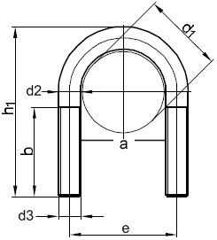
Nennmaß ( a ) mm 23 30 38 46 52 64 82 Rohr-Nennweite ( NW ) mm 15 20 25 32 40 50 65 Durchmesser ( d1 ) mm 20bis21 25bis26,9 30bis33,7 38bis42,4 44,5bis48,3 57bis60,3 76,1 Durchmesser ( d2 )
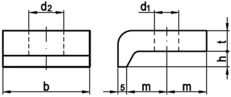
Durchmesser( h ) mm 10 12 14 16 18 20 Durchmesser( d1 ) mm 18 18 18 18 18 18 Durchmesser( d2 ) mm 24 24 24 24 24 24 Breite( b ) mm 60 60 60 60 60 60
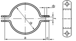
Durchmesser( d1 ) mm 22 27 34 43 45 49 Nennweite 15 20 / ¾" 25 / 1" 32 / 1¼" 40 40 / 1½" Durchmesser( d2 ) mm 11,5 11,5 11,5 11,5 11,5 11,5 Breite( f ) mm 7
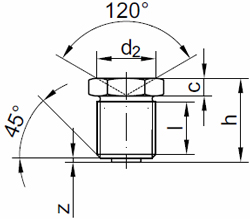
Gewindedurchmesser mm M 6 x 1 M 8 x 1 M 10 x 1 Durchmesser( d2 ) mm 6 8 10 Breite( c ) mm 3 3 3 Höhe( h ) max. mm 9,5 9,5 9,5 Gewindelänge ( l )
Gewindedurchmessermm M 6 x 1 M 6 x 1 M 8 x 1 M 8 x 1 M 10 x 1 M 10 x 1 M 16 x 1,5 Durchmesser( d2 ) mm 7,2 12 7,2 12 12 12 18
Gewindedurchmessermm G 1/4″ G 1/4″ G 1/4″ Durchmesser( d2 ) mm 12 18 18 Aussendurchmesser ( d3 ) mm 16 22 22 Aussendurchmesser( d4 ) min. mm 2,9 5 5 Breite( c ) mm 2 3 3 Höhe( h )
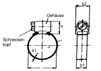
DurchmesserSpannberechnung ( d ) mm 8,0–16 12–20 16–25 20–32 25–40 32–50 40–60 50–70 Banddicke ( s1 ) mm 0,4–0,8 0,4–0,8 0,5–1,0 0,5–1,0 0,5–1,0 0,5–1,0 0,5–1,0 0,5–1,0 Bandbreite ( b1 ) mm 9/12+/-1 9/12+/-1 9/12+/-1 9/12+/-1 9/12+/-1 9/12+/-1 9/12+/-1 9/12+/-1 Gehäusehöhe